Wednesday, January 28, 2009

Default Subnets


The default subnet masks are three subnet masks that correspond to the standard Class A, B, and C address assignments.

Why Do We Subnet?

The IP addressing scheme was developed in the late 60s. It was never conceived at that point that so many organizations would want to access what is now called the Internet. The limited addressing space of 32 bits leaves us in a pickle for available bits.

Many people have experienced the same type of problem with voice addresses recently.

For instance, my area code changed from 904 to 850 because the phone company was running out of 904 addressing space. So in effect what the phone company created a sub-area with a different area code. Now the 850 area code is geographically inside what once was the 904 area code.

In the world of IP addressing the same idea was used as a solution to lack of addressing space. We will place one network inside another network. This is called subnetting.

Subnetting


A subnet is a network that falls within a Class A, B, or C network. Subnets are created by using one or more of the Class A, B, or C host bits to extend the network ID.

Subnet Masks

In order for subnetting to work, the router must be told which portion of the host ID should be used for the subnet network ID. It is accomplished by using another 32-bit number, known as a subnet mask.

Those IP address bits that represent the network ID are represented by a 1 in the mask, and those bits that represent the host ID appear as a 0 in the mask. As a result, a subnet mask always has a consecutive string of ones on the left, followed by a string of zeros.

Classifying IP Addresses


Class A addresses
Class A addresses are designed for very large networks. In a Class A address, the first octet of the address is the network ID, and the remaining three octets are the host ID. Each Class A network can accommodate more than 16 million hosts.

Class B addresses
In a Class B address, the first two octets of the IP address are used as the network ID, and the second two octets are used as the host ID. Each Class B address can accommodate more than 65,000 hosts.

Class C addresses
In a Class C address, the first three octets are used for the network ID, and the fourth octet is used for the host ID. With only eight bits for the host ID, each Class C network can accommodate only 254 hosts.

Sunday, January 11, 2009

Understanding IP Addresses

An IP address is an address used to uniquely identify a device on an IP network. The address is made up of 32 binary bits which can be divisible into a network portion and host portion with the help of a subnet mask. The 32 binary bits are broken into four octets (1 octet = 8 bits). Each octet is converted to decimal and separated by a period (dot). For this reason, an IP address is said to be expressed in dotted decimal format (for example, 172.16.81.100). The value in each octet ranges from 0 to 255 decimal, or 00000000 - 11111111 binary.
Here is how binary octets convert to decimal: The right most bit, or least significant bit, of an octet holds a value of 20. The bit just to the left of that holds a value of 21. This continues until the left-most bit, or most significant bit, which holds a value of 27. So if all binary bits are a one, the decimal equivalent would be 255 as shown here:
1 1 1 1 1 1 1 1
128 64 32 16 8 4 2 1 (128+64+32+16+8+4+2+1=255)
Here is a sample octet conversion when not all of the bits are set to 1.
0 1 0 0 0 0 0 1
0 64 0 0 0 0 0 1 (0+64+0+0+0+0+0+1=65)
And this is sample shows an IP address represented in both binary and decimal.
10. 1. 23. 19 (decimal)
00001010.00000001.00010111.00010011 (binary)
These octets are broken down to provide an addressing scheme that can accommodate large and small networks. There are five different classes of networks, A to E. This document focuses on addressing classes A to C.

Thursday, January 8, 2009

Pin - Connections for Twisted Pair

Creating Straight Twisted Pair Cable


Here are a few other points to remember when dealing with RJ-45 connectors and twisted-pair cable:

The pins on the RJ-45 connectors aren’t numbered, but you can tell which is pin 1 by holding the connector so that the metal conductors are facing up.


Some people wire 10baseT cable differently — using the green and white pair for pins 1 and 2 and the orange and white pair for pins 3 and 6. This doesn’t affect the operation of the network (the network is color-blind), as long as the connectors on both ends of the cable are wired the same!

If you’re installing cable for a Fast Ethernet system, you should be extra careful to follow the rules of Category-5 cabling. That means, among other things, making sure that you use Category-5 components throughout. The cable and all the connectors must be up to Category-5 specs. When you attach the connectors, don’t untwist more than 1.2 inch of cable. And don’t try to stretch the cable runs beyond the 100-meter maximum. When in doubt, have cable for a 100 Mbps Ethernet system professionally installed.

Creating Crossover Cable

Crossover Cables is a cable that you can use to directly connect two devices without a hub or switch.

You can use a crossover cable to connect two computers directly to each other, but crossover cables are more often used to daisy-chain hubs and switches to each other.

If you want to create your own crossover cable, you have to reverse the wires on one end of the cable.

Note that you don’t need to use a crossover cable if one of the switches or hubs that you want to connect has a crossover port, usually labeled Uplink. If the hub or switch has an Uplink port, you can daisy-chain it by using a normal network cable.


Installing Twisted Pair Cable


Installation Guidelines:

1.Purchase twisted-pair cable in prefabricated lengths, such as 50 feet, 75 feet, or 100 feet.
2.Always use a bit more cable than you need, especially if you’re running cable through walls.
3.When running cable, avoid sources of interference, such as fluorescent lights, big motors, X-ray machines, and so on.
4.The maximum allowable cable length between the hub and the computer is 100 meters (about 328 feet).
5.If you must run cable across the floor where people walk, cover the cable so that no one trips over it.
6.When running cables through walls, label each cable at both ends.
7.When several cables come together, tie them with plastic cable ties.
8.Cable ties have all sorts of useful purposes.
9.When running cable above suspended ceiling panels, use cable ties, hooks, or clamps to secure the cable to the actual ceiling or to the metal frame that supports the ceiling tiles.

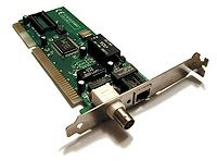
Network Interface Card Installation Guide


1.Gather up the network card and the driver disks.
2.Shut down Windows and then turn off the computer and unplug it.
3.Remove the cover from your computer.
4.Find an unused expansion slot inside the computer.
5.When you find a slot that doesn’t have a card in it, remove the metal slot protector from the back of the computer’s chassis.
6.Insert the network interface card into the slot.
7.Secure the network interface that you removed in Step 4.
8.Put the computer’s case back together.
9.Plug in the computer and turn it back on.